
Please send us your Enquery


Our Services

 Tank
Tank
Calibration
 Tank Settlement
Survey
 Industrial NDT
Consultancy
 Pipelines Survey
 Weighing Scales
 Prover Tank
 Area of Service
 Ship Tank Calibration
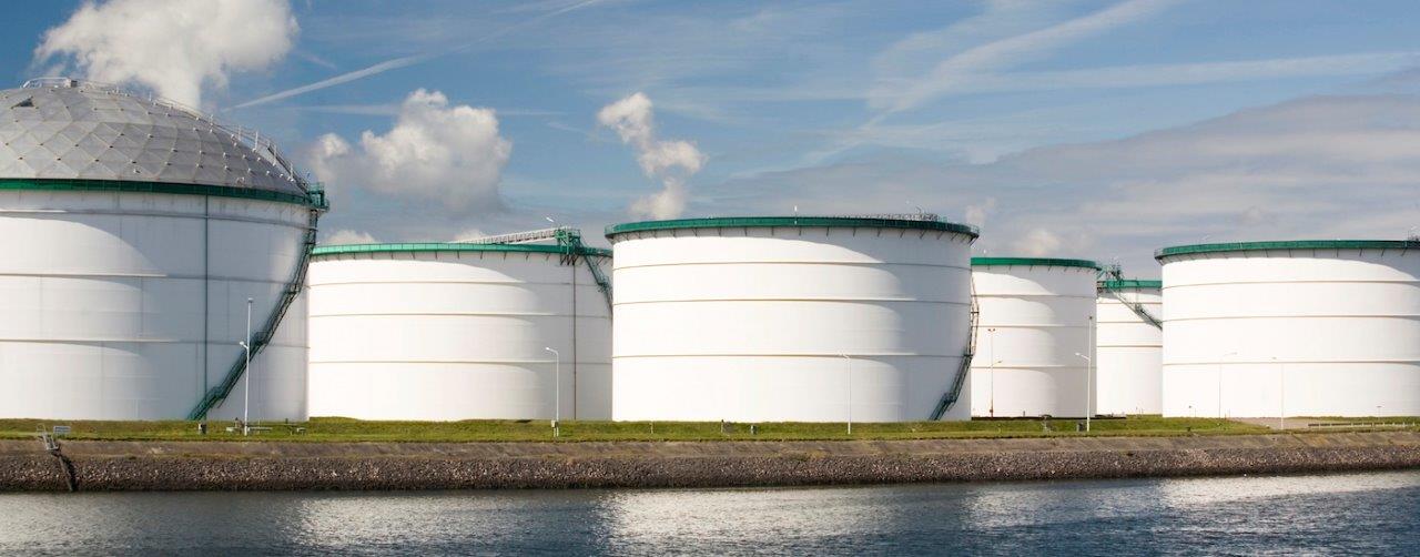
Tank Calibration
Tank Calibration is the process of accurately determining the capacity or partial capacities of a tank and expressing this capacity as a volume for a given linear increment or height of liquid. In other words tank calibration also means measuring storage tanks, horizontal bullets, spherical tanks, vats, casks, barges, ship tanks and liquid bulk containers. These measurements provide the necessary dimensions for calculation of calibration charts.
At its simplest, a calibration of any vessel requires knowledge of the nominal dimensions of the vessel from which the volume may be calculated. For a water tank this may be enough and you probably will not need to call in a specialist tank calibrator.
At the other end of the scale, if you are selling a product on the basis of tank levels, a tank can be measured precisely and calculations can be made to take into account factors such as hydrostatic expansion of the tank during filling and thermal expansion of the tank shell in service.
For most situations in India or anywhere in the world where you are selling from a tank or where duties are levied on tank contents you will need to have a tank calibrated by a suitably certified tank calibrator. For the purposes of this exercise we shall assume that you have decided that you do require a precise calibration of your tank.
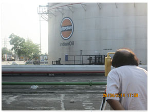
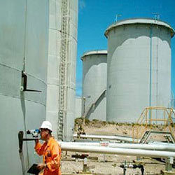
Tank Settlement & Survey
If we consider a Steel Storage Tank like a plastic bucket, when we pour water into the bucket the plastic walls tend to expand then again come back. After we have filled the bucket full, we notice that the top rim of the bucket tends to be slightly elliptical instead of circular in shape. When we stir our hand inside water we notice that the bucket walls tend to wrap. Same thing happens with the large storage steel tank of oil, chemical. As it is daily filled in and out with oil, chemical there tends to be deformation of the tank walls, pressure on the tank floor and specially if it is a floating roof tank, the roof due to uneven foam seal gap. Also due to enormous weight of liquid pressure exerted on the tank bottom, the tank bottom tends to subside which can cause cracks in joints and make the tank tiled on one side gradually affecting centre of gravity.
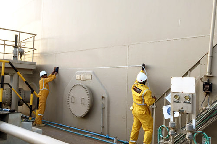
The tank can also tilt to one side due to uneven liquid head pressure. All this phenomenon is called out of roundness, tank tilt and tank floor settlement. If these are not studied and a detailed report made where you can repair, you can understand the catastrophe and safety/technical issues involved. It is this tank health that needs to be studied under API 653 B standard. To measure, study, analyze and make proper reports is very difficult. We have lots experience in the field of tank calibration since 1983, which make us expert to study the tank health with our accurate Total Station, Laser equipment and experienced engineers. After a few years of use, large tanks should always be studied for tank roundness, tilt and bottom settlement. We have mastered this technique of tank health checkup which can also include a detailed ultrasonic thickness report of tank floor and shell as floors can corrode over time, especially MS tanks. So when tanks are decommissioned for any repair or cleaning, they should be studied as mentioned above. Just do the call or mail us. We are available to do this study around the world
BROCHURE-SURVEY & INSPECTION BROCHURE- ROUNDNESS TESTIndustrial NDT Consultancy
Services : Other various specialized services such as
- Assessment of Storage Tank
- Eddy current testing of condenser tubes, feed water heater, heat exchanger tubes and air conditioners.
- Tube inspection with IRIS.
- Positive Material Alloy Identification (PAMI) in-situ mettallography for the identification of metal / alloy type..
- Assessment of micro structural condition where removal of test specimen is not possible.
- Identification of metal corrosion under insulation (CUI)
- Material Identification (PMI) and Weld Inspection.
- Time of Flight Diffraction (TOFD) Test
- 3D Laser Calibration
Radiographic Testing (RT)
Majority of the welding works on pipes require a Radiographic examination of the weld. RT is performed to inspect the quality of the weld and ensuring that the weld is free of bubbles or foreign material inclusions which will compromise the strength and integrity of the weld. The flaw can be observed on the film where the Radiographic image is recorded, similar to the medical X‟Ray image.
M/s. Girish Chandra Ghosh & G.G.S. prides itself in training technician in house, to international standards. Our technicians are trained by highly experienced Level- III staff engineers who have a vast experience in the industry.
M/s. Girish Chandra Ghosh & G.G.S. technicians are highly experienced in the use of Ir- 192 and the X‟Ray tubes. Our safety performance, especially, in the operation of Radioactive Sources are highly exceptional. This skill has enabled M/s. Girish Chandra Ghosh & G.G.S. to become the preferred NDT Contractor for Radiography works especially in high profile area.
Liquid Penetrant ( LPI) & Magnetic Particle (MPI) Inspection
Both the RT & UT techniques can miss the imperfections present at the surface of a weld or metal. Hence, depending on the material, LPI or MPI technique is performed.
A bright colored penetrant is sprayed on the surface of the metal. Any cracks or surface imperfections will draw the penetrant into it. After the excess penetrant is cleaned, an even layer of developer is then sprayed on the surface. This will draw out the penetrant and make the imperfections visible.
The LPI technique is applicable to any material that is non- porous
On a clean ferromagnetic material surface and sub-surface, any imperfection will create a disturbance in the magnetic field. The material is normally magnetized by a magnet yoke
and the test agent applied. Patterns will form around the imperfections which will make them visible and their nature and size classified.
The MPI Technique is good for tracing narrow surface defects.
Ultrasonic Testing (UT)
There is variety of welding where Radiographic examination could not be performed, typically due to geometry and inaccessibility of one side or both. UT techniques are then used to inspect these welds. This is a kin to a radar “ping” which is reflected from the boundary of different acoustic impedance in its path.
An ultrasonic wave is projected into the material surrounding the weld and its reflection analyzed. A well- trained UT technician is able to spot a minute flaw in the weld by analyzing the UT wave on the oscilloscope. M/s. Girish Chandra Ghosh & G.G.S. prides itself in training its technician to ASNT Level II standard, in-house, and equipping them with a few years of field experience. Hence, the technicians would have the required experience and qualifications to expertise the services in various field certainly not limited to structural weld inspection (AWS D1.1), off-shore structural weld (API RP-2X), Tubular Inspection (ASTM SA 213) and pressure vessels (ASME Sec VIII Div 1 & 2) Inspection.
M/s. Girish Chandra Ghosh & G.G.S. highly trained experienced and dedicated technicians are deployed at major onshore and off-shore projects in India and abroad.
In addition to the conventional NDT techniques, M/s. Girish Chandra Ghosh & G.G.S. also performs other services such as UT thickness gauging, coating measurement, hardness testing and holiday detection among others.
Heat Treatment Services
General Introduction
Advanced technologies demand the latest and higher quality parts and components of various alloy steels attached together. The most ideal way to attach these materials is through welding. However, an enormous amount of heat is generated during welding that induces thermal stresses. Therefore it is necessary to remove these detrimental stresses through the proper application of heat treatment.
Electric Resistance Localized Post Weld Heat Treatment
In-situ localized preheat and post weld heat treatment of pipe butt welds, welding seams on vessels and storage tanks, inclusive of other weldments, forgings and castings.
Each 70kVA and 50 kVA transformer comes complete with energy regulator/temp. Control unit for type „K‟ Thermocouples, providing semi- automatic control facilities.
- Each unit capable of powering upto 24 x 60 V rated ceramic pad heaters/ cycle.
- Safe power output of upto 80 V ratings maximum, designed to comply with industrial safety regulations and restrictions.
- Thermocouples are attached to work piece by direct wire capacitance discharge method using our thermocouple attachment Units.
Hardness Testing Services
Brinell & Equotip Techniques
- To measure material hardness after heat treatment, we offer Equitip Technique.
- Recognized and accepted by the engineering community to be reliable in producing very accurate results.
TOFD
Time of Flight Diffraction
Pressure vessels welds are often thick, so are the welds on bigger diameter pipes meant for high pressure services. Inspection of these welds with Radiography techniques require long exposure times. The speed of the construction today and the critically of these equipments require high accuracy defect sizing is combined with high inspection speed.
TOFD is able to measure defect lengths accurately through some thickness height, which are the key parameters in mechanical strength calculations. The speed of which the Inspection can be done, the accuracy and not forgetting the elimination of radioactive sources make this technique very attractive indeed.
TOFD Principle
TOFD Inspection applied two sets of ultrasonic probes on either side of the weld. The transmitter probe emits a wide angle beam covering the complete weld volume and heat affected zone in one scan. Thicker components (>50mm) are subdivided in several depth zones. Possible defects diffract the sound beam at the upper and lower defect tips and the receiver probe picks up diffraction signals.
Accurate Defect Sizing
Defect sizing is based on position mapping of the diffraction signals. The defect height can be readily measured by straightforward subtraction of lower and higher tip positions. A typical figure for the accuracy that may be achieved in through thickness height measurement is 0.5mm. Surface breaking defects are discriminated from embedded
defects; volumetric defects from planer ones. An important advantage of TOFD compared to conventional Ultrasonic and Radiography, is high probability of detection, virtually independent of its defect orientation.
TOFD Weld Inspection during Fabrication and Online
Minimal surface preparation is required. Typically power brushing just to clean the surface is sufficient. A couplant which is in the form of corn starch or water can be used.
TOFD may also be applied during construction (while the welding personnel are around.), where time constraints exist. In contrast to Radiography, TOFD allows examination directly after welding (up to 200ºC) without holding up the production speed or evacuating personnel working nearby; acceptance of results is directly available onscreen or as a hard copy printout. TOFD is a fast and cost- effective alternative to Radiography.
In contrast with radiography again, for TOFD examination on external access to the object is required for a certain thickness to reduce the exposure time (for SWSI) technique). In the service stage of process installations and pipe work, TOFD may be applied „on stream‟ to inspect equipment, while it remains in service. „Fingerprints‟ of the object are taken to monitor initially acceptable defects and reveal and progressively monitor service induced defects.
TOFD Applications
TOFD is acceptable for weld inspection of pipes or plates in a thickness range of 6mm upward (also heavy vessels upto 300mm can be examined.), pipe to plate nozzles, complex joints etc. All types of welding defects including lack of side wall fusion and root penetration can easily be detected and sized. For TOFD Inspection, the feasibility of coarse-grained materials such as several types of austenitic steel is usually assessed on a case to case basis by means of test specimens. Varying concentrations Ni and Cr alloys as well as duplex materials can be inspected successfully
Capabilities
- Largely independent of flaw orientation for detection.
- Measures the through –thickness height of flaws accurately.
- Most sensitive to planar flaws, but can detect all types of flaws.
- Better probability of detection than conventional UT or RT.
- Achieves a better false call rate than conventional UT.
- Work at high surface temperature, upto 200º C
- Immediate on-screen result, hard copy print out and storable data.
- Inspection of on-line pipes/vessels are easily analyzed with repeated inspection on the same spot annually.
- A-Scan, B-Scan and D-Scan results are available.
Considerations
- Difficult to apply to thin material < 8mm
- Difficult to apply to complex geometries, nozzles and nodes.
- Difficult to radially position flaws in the weld or between probes
- Flaw characterization and positioning with conventional UT
Considerations
Maintaining process temperature is important as variations in temperatures could have an adverse effect on a plant‟s efficiency and in some operations can affect the products qualities. Heat exchangers keep various production or operating circuits at their desired design temperature. As these exchangers operated at elevated temperatures and pressures, they are bound to have wear and tear associated with these operations. Some exchangers are exposed to potential marine growth. Leaks due to this can have extended effect to possibly turbine blades in power plants. M/s. Girish Chandra Ghosh & G.G.S. offers comprehensive heat exchanger maintenance and inspection services complete with scaffolding and pressure testing.
Eddy Current Testing
The most effective inspection technique for heat exchanger tubes is Eddy Current testing. Furthermore, Eddy Current Test method is best solution for the surface and sub-surface imperfection test on non-ferromagnetic materials.
It works by measuring the impedance of a coil. The impedance of the coil changes as the electromagnetic field interacts with the material. Initially, the coil is placed in the tube and balanced on the defect free material. As the probe is pulled, the variations in the coil impedance are recorded.
The impedance changes are related to the type and size of defects. For accuracy, the calibration is performed on a tube machined according to ASME section V Article 8.
PMI
Positive Material Identification
Having a material mix-up is not just costly. A catastrophic failure is also a possible consequence. Plant owners now insist on ensuring that material received at the fabrication site conform to the specifications as having the MIL certification is no longer a sure means of material quality control. It is also important to be able to identify and grade materials quickly. New Technology has enables manufactures to produce highly portable machines with comprehensive inbuilt libraries for quick sorting and grading.
Established Industry Standard
Where the user would prefer a known machine or method, M/s. Girish Chandra Ghosh & G.G.S. would offer the X-Met 5000. This is because Oxford Instrument has long been the specified machine of many plant contractors for more than 30 years. With this machine, the user not only has a proven track record, but the options to utilize either the fundamental parameters (FP) or empirical calibrations as well.
NDT CONSULTANCY BROCHUREPipelines Survey
We do P & I Drawing, Isometric Drawing, Quantity Survey, and Pipeline Health Survey as per our customer requirement. We perform the job at first in site inspection & then we submit report for this same in Soft & Hardcopy. We maintain engineering principle with accuracy in work in specified time.
Weighing Scales
WEIGHING SCALES
OUR MODELS ARE APPROVED BY GOVT. OF INDIA, Ministry of Consumer Affairs, Food & Public Distribution Department of Consumer Affiars
Introducing ourselves as a Govt. Licensed Manufacturers, Repairers & Dealer of Weighing Machines (Electronics & Mechanical) both, and approved License Holder of Legal Metrology Dept. (Weights & Measure) Govt. of West Bengal. We design, develop and offer an extensive array of electronic weighing scales that is high in performance, durable in quality and give optimal output to the clients.
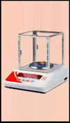
Jewellery
ScaleWe also fabricate high quality Jewellery scales that are widely used in Jewellery shops to measure weights of different jewelleries. Providing exact precise measurement these scales are designed and developed to measure different weight range in an easy way.
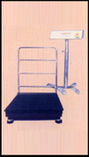
Platform
Scale To cater to diverse needs of our customers we are offering range of portable platform scales that can measure the weight of objects (heavy or light) that is placed on the platform. Specifically designed platform scales are available in sizes, capacities and models. Thus allowing our customers to select as per their requirement.
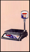
Table
Top Scale High quality table top deluxe is available in reliable design that is most suitable for its effective performance. These portable table top measuring instruments are fabricated with fast weighing response, battery back-up and red/green led display that facilitates accurate result and easy readability.
Prover Tank
Proving tanks shall be provided with drain valves at the bottom part; they should be designed with a top neck and may be designed with a bottom neck. The requirements given in Standard Test Measure on the diameter of the neck of standard test measures apply equally to the diameter of the top and bottom necks of proving tanks.
The top neck should be provided with glass plates or a separately fixed gauge glass(es), on which the scale marks corresponding to the nominal capacity and to variations of at least 1 % of the nominal capacity, in plus and in minus, are marked. Otherwise, the top neck part shall be fitted with a fixed and rustproof metal plate or a sliding plate capable of being sealed and on which the scale marks corresponding to its nominal capacity and to the volumes below and above the nominal capacity, are marked.
The bottom neck should be provided with glass plates or a separately fixed gauge glass(es) similar to the top neck, with scale marks corresponding to volumes of only 0.5 % in plus or in minus of the nominal capacity.
The diameter of the gauge glasses connected to the top and bottom necks shall be large enough to ensure that capillary or meniscus effects do not introduce additional uncertainties such that the maximum permissible errors (±½ 000 of the nominal capacity as given in clause 2.2.2.2 of OIML R 120) are exceeded.
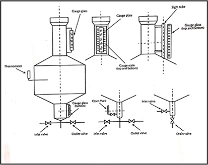
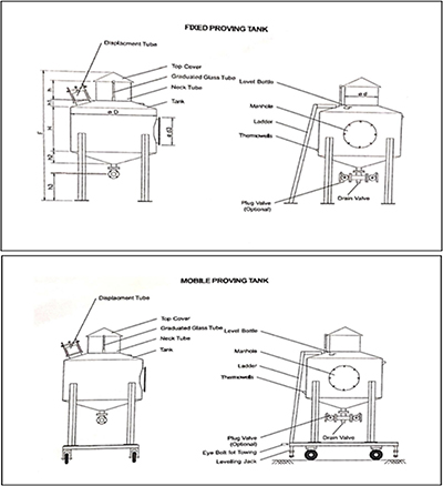
Figure: 1
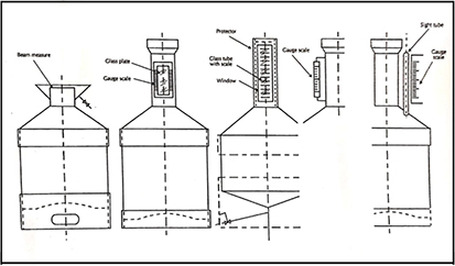
Figure: 2
It shall be ensured that the liquids are easily delivered to and from the proving tanks and that no pockets, dents or crevices capable of trapping the liquid, air or vapor are present.Examples of different designs of a proving tank are shown in Figure 2.
The proving tank shall be provided with means for measuring the temperature of the liquid it contains.
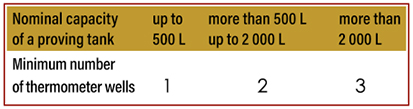
When thermometer wells are used for determining the temperature of the test liquid in the proving tank, the minimum recommended number of thermometer wells is given in Table 2.
Table: 2
STAMPING AND SEALING ARRANGEMENT:
The image shows a diagram of a stamping and sealing arrangement, with a focus on the adjusting device and the manhole cover. The diagram illustrates how a sealing wire is used with a seal for security.
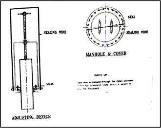
Figure: 3
The sealing is done by a seal wire is passed through the holes provided at the top graduated scale which is sealed to stop the fraudulent practices. A typical schematic diagram of sealing provision to prevent the fraudulent practices of the model is given above as Figure 3.
SKETCH AND DRAWING:
TEST PROCEDURE FOLLOWED BY MANUFACTURE:
The test procedures described in clauses 6 to 12 may be used for the testing of the following typical measuring systems:
CLAUSE 6: Meter on its own or fitted with ancillary devices
CLAUSE 7: Fuel dispenser
CLAUSE 8: Measuring system on a road tanker
CLAUSE 9: Measuring system for the unloading of road and rail tankers, ships' tanks and tank containers
CLAUSE 10: Measuring system for the loading of road and rail tankers, ships' tanks and tank containers
CLAUSE 11: Measuring system fitted into a pipelineclause 12: Measuring system for milk
The thermometer well shall be deep enough to enable the correct immersion of a thermometer and shall consist of a metal socket with good heat conductivity having one end closed; it shall be inclined so that liquid can be added to the well if desired. The thermometer wells shall be installed with such an immersion that the ambient temperature outside the proving tank will not affect the thermometer.
When the installation of two or three thermometer wells is recommended, these shall be installed in accordance with the following location conditions:a) in the upper and lower half of the main body, or in the upper and lower third and near the center of the main body of the proving tank, andb) at two or three points, equally spaced around the circumference of the proving tank.Where proving tanks are mounted on a truck or trailer, means shall be provided to secure and maintain them in a level position, during testing and use.For testing certain types of measuring systems (for example, those for the recep¬tion of milk), it may be easier to use proving tanks of the brim measure type.
MATERIALS OF CONSTRUCTION:
BODY : Carbon steel (internally epicoated), Stainless Steel
DISPLACEMENT TUBE : Carbon steel (zinc plated / yellow passivated), Stainless Steel
GRADUATED GLASS : Borosil glass
THERMOWELLS : Carbon steel
DRAIN VALVE : Carbon Steel, Stainless Steel
Area of Service
- TANK CALIBRATION/RE CALIBRATION
- SETTLEMENT SURVEY
- OVALITY SETTLEMENT SURVEY
- TERMINAL SURVEY
- HEALTH SURVEY OF TANK & PIPELINE
- ROUNDNESS CHECKING OF STORAGE TANK
- NDT(NON DISTRACTIVE TEST)
- UST(ULTRASONIC TESTING)
- DIFFERENT TYPE OF DRAWING (ISOMETRIC AND P &ID DRAWING)
- FLOW METER RE-VERIFICATION &STAMPING
- DIP TAPE & DIP STICK SUPPLY
- RADIOGRAPHY REPORT
- REMOTE VISUAL INSPECTION
- MAGNETIC FLUX LEAKAGE TESTING
- HEALTH STUDY OF OLD EQUIPMENTS,STRUCTURES ETC (RLA),RLA-RESNDIAL LIFE ASSESMENT)
- VALUATION OF ESTABLISHMENT
- MAGNETIC PARTICALE TESTING
- PENETRANT TESTING
- API-653 TANK INSPECTION
- API-570 PIPING INSPECTION
- VALVE TESTING FOR SAFETY
- SURVEY /INSPECTION AND NDT WORK
- WEIGHING MACHINE SUPPLY & RE-VERIFICATION(WEST BENGAL ONLY)
- WEIGHT & MEASURE MANUFACTURER/REPAIRER/AMC/DEALER
- WEIGHT & MEASURE ITEMS SOLUTIONS
- LIQUOR MEASURES MANUFACTURER/SUPPLY
- 3D LASER TANK CALIBRATION
- TANK CLEANING
- PAINTING JOBS
- CIVIL & MECHANICAL WORK
- INSPECTION WORK
- SURVEY WORK
- DRAWING WORK
- Weigh Bridge(Repair & Service)
- PROVER TANK MANUFACTURER
- WEIGH SCALE MANUFACTURING SERVICES & SUPPLY
- VOLUMETRIC FILLING MACHINE & GRAVIMETRIC FILLING MACHINE (REPAIR , REVERIFICATION AND ASSISTANCE WORK AS REPAIRER IN WEST BENGAL / SIKIM / ASSAM)
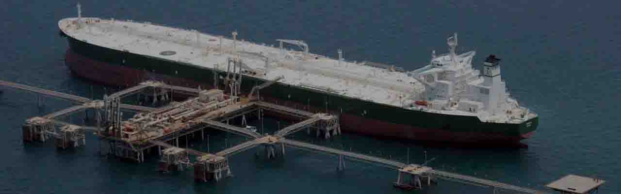
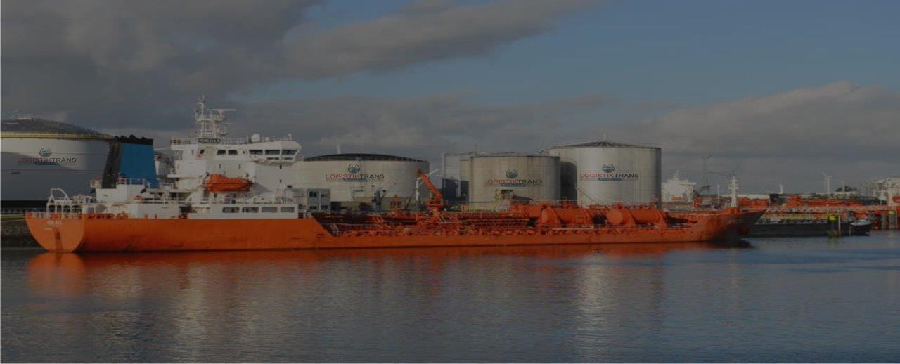
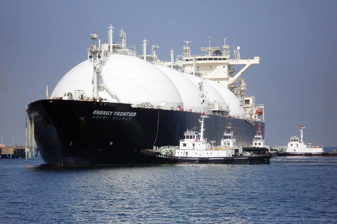
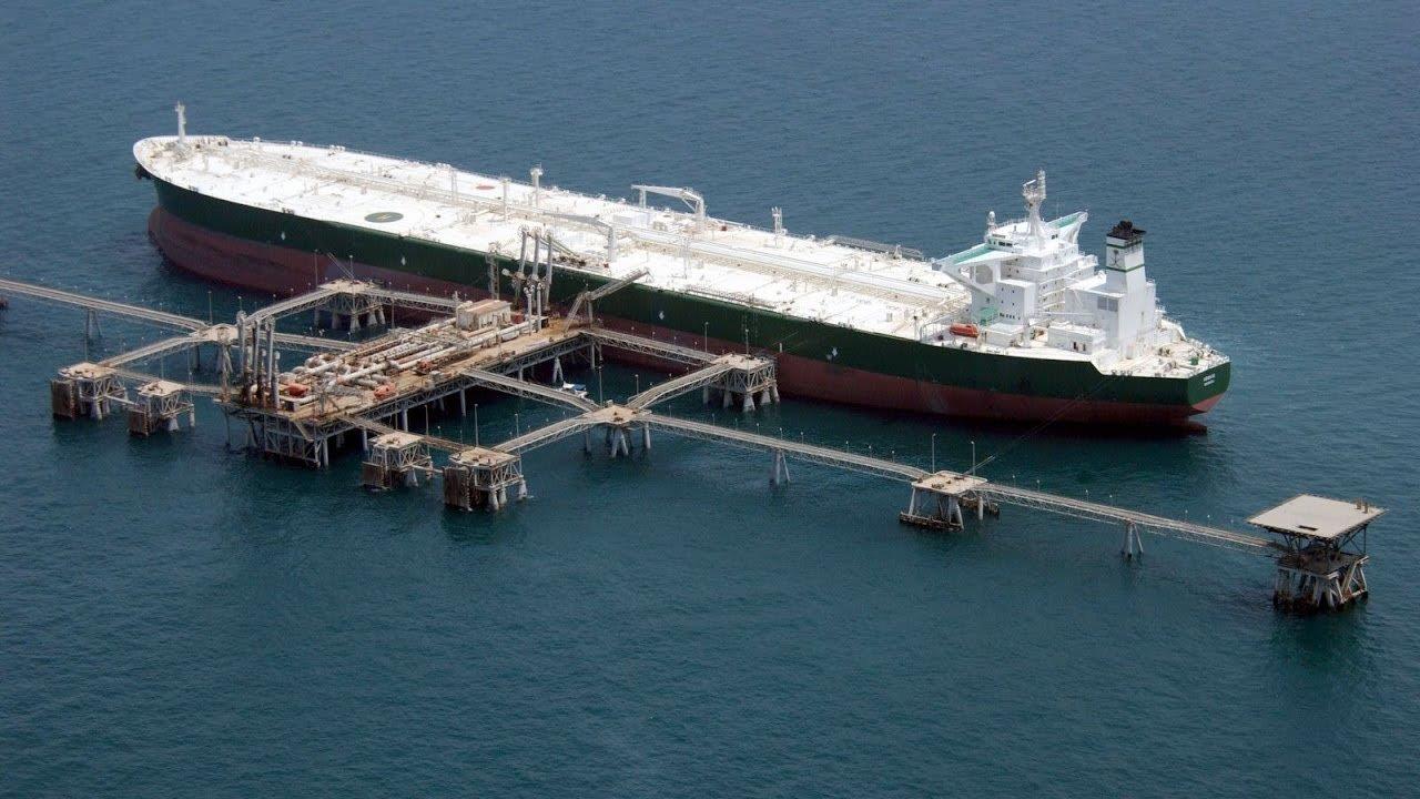
Ship tank calibration
To ascertain gain or loss in sales, purchases to provide only reliable means of maintaining adequate control over the storage & distribution & stock keeping & in industrial production process control, as Oils, chemicals & its allied products are very costly items business & service render from it. Profit & Loss depends on accuracy of ship tank or barge storage tank calibration work.
By using laser scanning and an extremely accurate and fast scanner supported by a powerful software. It is ideal for every ship, but especially for floating storage vessels, delivery barges, chemical tankers, bunker tanks etc, where accuracy is of utmost importance
No matter the shape of the tank or the deadwood inside, you can have tables accurate at any level. List and trim corrections are calculated accurately without the approximations and restrictions of the old style trigonometric methods Field measurements can be done in hours; hence there is no need to have your vessel waiting days to be calibrated.
Our skill and understanding of every tank detail and the ability to incorporate them into final tables makes us stand out among the crowd. We use the most accurate, reliable and fastest laser measurement systems available. International Method followed: API MPMS
 BROCHURE-SHIP TANK 1 BROCHURE-SHIP TANK 2